
Blog
A Centrifugal Duct Fan Supplier Brief for Constrained Inline Installations

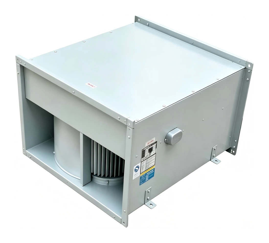
The fan may fit the ceiling void and still be impossible to install through the available hatch. For a contractor choosing a centrifugal duct fan supplier, the practical starting point is the complete route into position, followed by the required airflow and pressure. TWOSUN lists the GDF centrifugal duct fan, alongside SWF and HL3-2A mixed-flow fans, HTFC-III cabinet fans and ventilation silencers. Use GDF as the initial centrifugal duct-fan route, then compare alternatives against the same duty and access constraints. A nominal duct diameter does not describe the delivered assembly or the space needed to maintain it.
Picture a commercial refurbishment with a finished corridor, a narrow access hatch and an existing duct route above the ceiling. The ventilation requirement is known, but the contractor has only a small opening through which to introduce the fan. The equipment brief must therefore answer three separate questions: can it enter, can it connect, and can it be serviced after the ceiling is closed?
A centrifugal duct fan supplier needs the access route before the final enclosure is approved
TWOSUN presents GDF as a centrifugal duct-fan configuration. The selected size and arrangement need a general arrangement drawing that can be compared with the actual installation route. Request the delivered envelope and identify any projections or supplied components that affect passage through the opening. Do not assume the unit can be dismantled simply because the project has a narrow hatch.
The GDF delivery envelope is different from its duct connection
A connection dimension describes a mating air path, not the outer size of the fan assembly. Supports, electrical access and the enclosure can extend beyond that connection. Keep the drawing’s overall dimensions and connection dimensions clearly labeled. The contractor should check the complete assembly against the hatch and the available turning space.
For the refurbishment scenario, measuring only the clear hatch width would miss a second constraint: the fan may need to turn after passing through the opening. Show the nearby structure and services that restrict that movement. Ask the supplier to confirm the proposed delivery arrangement, then have the installation team verify that its handling method is feasible for the actual space.
A simple drawing review can separate these dimensions without inventing a product limit. Mark the fan’s delivered width, height and length from the selected GDF drawing, then mark the access route independently. Include any lifting or handling allowance required by the installation method. A comparison of two nominal widths is insufficient where the assembly must rotate or pass an obstruction immediately after entering the hatch.
HTFC-III cabinet alternatives can change the route into the ceiling or plant room
TWOSUN lists HTFC-III as a backward centrifugal cabinet range. It is a possible separate comparison where a cabinet arrangement suits the system, rather than an automatic replacement for GDF. Review the selected cabinet’s envelope, access faces and connections against the route. A different enclosure may resolve one constraint while creating another.
The HTFC cabinet arrangement and operating-mode guide follows the motor-location and service questions behind that alternative.
If a cabinet option requires a plant-room location instead of the ceiling position, revisit the duct route and resistance. The original GDF duty may no longer describe the revised system. The value of an alternative arrangement lies in solving the whole installation problem, not merely in finding an assembly with a shorter dimension in one direction.
GDF centrifugal duct-fan performance must match the completed air route
Provide the required airflow and the pressure basis at stated air conditions. Include the resistance of the actual route, including terminals, dampers, silencers and other relevant components. A fan’s maximum airflow is not the airflow available against every duct resistance. Ask for the selected operating point and the corresponding motor and speed information.
A GDF selection should retain one consistent static or total pressure basis
The project designer should define the pressure requirement and system boundary. Keep that definition in the enquiry and the final offer. ASHRAE’s fan guidance discusses pressure selection in relation to the system arrangement. The applicable basis should be established by the engineering design rather than guessed from an unlabeled pressure figure.
If the original schedule came from a different fan position, check whether it includes the final duct route. A GDF unit moved farther along the corridor may see additional bends and duct length. That revised route needs review before the old duty is reused. Record the revision in the fan schedule so purchasing and the installer work from the same information.
SWF and HL3-2A alternatives need equivalent duty information
TWOSUN’s SWF and HL3-2A ranges provide mixed-flow options for a separate technical comparison. They should be assessed at the same required flow, pressure and inlet conditions as the GDF proposal. Do not compare a mixed-flow catalogue maximum with a centrifugal selection made at a specified resistance and call the difference extra capacity.
AMCA’s explanation of fan curves helps keep that comparison tied to a common operating point. The selected performance, power and dimensions belong together. A compact alternative is useful only if its selected duty and installation conditions remain suitable for the project.
Keep the intended operating modes visible as well. If the building uses different ventilation settings at different times, ask for the proposed equipment and control arrangement for those modes. The existence of an adjustable electrical control does not independently establish acceptable performance throughout an unspecified range.
For an existing system, distinguish measured operating information from the original design schedule. If the GDF replacement enquiry uses a field airflow reading, explain the operating mode, damper positions and measurement method. If it uses the original design duty, identify any changes since that design. The supplier can then review the evidence without mistaking a restricted existing condition for the ventilation capacity the building actually needs.
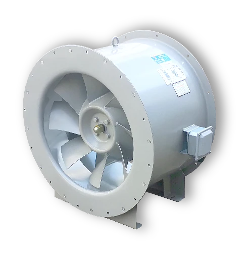
The GDF connection drawing should show what happens immediately before and after the fan
A straight connection path is often assumed in an equipment schedule even when the ceiling layout forces a bend beside the fan. Send the actual inlet and outlet geometry to the supplier. Technical guidance on fan system effects explains why nearby elbows and abrupt transitions can affect installed performance. It is general engineering background, not a prescribed TWOSUN connection detail.
A tight GDF inlet turn needs review before the fan is sped up
If the inlet arrangement differs from the conditions behind the performance data, ask the supplier and designer to review it before approval. The response might involve a revised fan position, transition or selected arrangement. Do not assume a motor-power increase can compensate for every poor inlet condition without consequences for sound, power or mechanical operation.
For a late refurbishment change, retain the approved fan selection while reviewing the changed duct sketch. That makes it possible to identify what changed: the equipment, the system or both. Without that comparison, a site team can spend time replacing a correctly supplied GDF unit while leaving the new restrictive connection untouched.
Silencer dimensions belong in the GDF layout from the beginning
TWOSUN lists ventilation silencers among its system components. If the project needs one, obtain the selected dimensions and pressure-loss information early. Include it in the fan duty and the physical route. A silencer added after the GDF assembly is fixed can consume the space reserved for access or introduce resistance absent from the original selection.
The acoustic function also needs a defined path and requirement. A duct silencer does not automatically address sound radiated from a fan enclosure into the ceiling void. The guide to source sound and occupied-space assessment explains that distinction. Use the project acoustic assessment to decide what equipment data and treatment are needed.
A service route for the centrifugal duct fan must survive the finished ceiling
Installation access is temporary; maintenance access has to remain. For the selected GDF assembly, request the manufacturer’s service requirements and identify which components need to be reached or removed. Show the access face on the coordinated ceiling drawing. A hatch located beside a fan is useful only if it gives access to the relevant work.
A second buyer scenario is a maintenance replacement in an occupied building. The old unit may have entered before partitions and cable trays were fitted. Its removal route no longer proves that a new assembly can be installed. Survey the current route and explain what will remain in place before the supplier finalizes a GDF or cabinet alternative.
For an HTFC-III option, confirm the required door or panel access. For SWF or HL3-2A equipment, confirm the relevant motor or assembly access for the selected arrangement. Do not copy one fan family’s service envelope onto another. The installation should follow the instructions for the equipment actually supplied.
Agree which surrounding items are intended to be removable for service. If a GDF arrangement depends on removing a duct section, identify that section and its access requirements on the coordinated drawing. The installation team should confirm the work can be performed without disturbing unrelated services. A removable component shown on paper does not provide access when its fasteners or handling space are concealed by the finished building.
Coordinate the electrical access with the same care. The isolation and connection arrangements need to suit the installed position and the project’s electrical design. A cable route that crosses the intended component-removal path can turn a serviceable fan into a difficult replacement job. Resolve that physical conflict before the surrounding services are completed.
Give the GDF order a clear boundary between fan, ductwork and supporting components
State which items the fan supplier provides and which belong to the duct or installation package. Identify transitions, supports, flexible connections, dampers and silencers where they are required. TWOSUN’s portfolio includes several system components, but their presence in the range does not mean they are automatically included with every GDF quotation.
For the selected assembly, align the equipment tag, motor information, airflow direction, connection dimensions and approved drawing reference. TWOSUN describes aerodynamic measurement and mechanical inspection in its testing information. Agree the records relevant to the selected fan rather than treating general laboratory capability as an order-specific result.
When equipment is packed for delivery, preserve the installation identity. A GDF assembly and a separately supplied silencer should be marked so the receiving team can match them to the approved system. TWOSUN shows wooden export packing; actual package dimensions, support and storage instructions need confirmation for the order. The packed equipment also has to reach the building’s receiving and staging areas.
Where several GDF units serve different zones, keep the approved duty and electrical arrangement with each equipment tag. Similar enclosures can hide different selections. The receiving team needs a reliable match between the delivered unit and its intended position, while commissioning needs the corresponding operating information. Confirm that identification before the assemblies are distributed through the building and their packing documents become separated.
Before release, take the final drawing through the same three questions used at the beginning. Can the delivered fan enter through the route? Can it connect while preserving the selected duty? Can its service components be reached after completion? A GDF, mixed-flow or cabinet selection becomes practical when all three answers refer to the same approved assembly.
