
Blog
DTF Metro Axial Fan Manufacturer Decisions at the Ventilation Interface

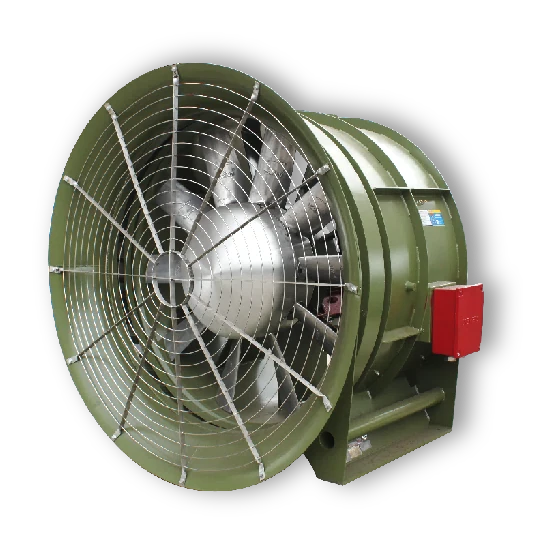
The fan-room drawing often reaches the equipment buyer after the civil layout is nearly fixed. At that stage, selecting a DTF metro axial fan manufacturer is as much an interface decision as a performance decision. TWOSUN’s metro and tunnel range includes DTF axial fans, DTF(R) arrangements, vertical configurations, inlet flares, dampers and silencers. Metro contractors and ventilation engineers should start by agreeing the operating duty and airflow direction, then check the complete installed length and maintenance route before approving a configuration.
The essential distinction: a duct-connected DTF axial fan moves air through a defined ventilation route. An SDS jet fan has a different role in longitudinal air movement. Their shared tunnel application does not make the two products interchangeable.
A DTF metro axial fan manufacturer needs an operating-mode schedule
The operating-mode schedule should describe what the fan is expected to do in each relevant condition. Distinguish routine ventilation from any specified emergency smoke-exhaust duty. State airflow and pressure together, identify the pressure definition and note the air condition used for selection. Where the system requires reverse operation, provide the reverse duty explicitly rather than assuming that a forward-duty curve describes the entire requirement.
DTF-7.1 and DTF-18 are equipment references, not complete duty definitions
TWOSUN presents DTF-7.1 and DTF-18 axial-flow configurations in its product range. These names help locate real equipment families, but they do not identify a complete motor, speed, blade setting, operating point or installation drawing. A buyer should preserve the full selected designation in the technical submission. Shortening the reference to DTF because the units share an appearance can make an equipment schedule too vague for manufacturing or acceptance.
The company-supplied metro catalogue describes a small-size DTF range with impeller sizes from 355 to 1120 mm, maximum airflow up to 100,000 m³/h and total pressure up to 1500 Pa. Those are catalogue envelope figures for that described range. They are not one simultaneous duty point, and they do not define every larger DTF configuration shown elsewhere. Select from a particular curve and drawing, with the relevant model and conditions attached.
A metro contractor specifying several fan rooms may therefore need more than one DTF arrangement even when the airflow figures look similar. A unit connected to a long discharge route may face a different pressure requirement from one close to an external opening. Copying the first room’s selection into the second can hide that difference. Preserve each system reference until the technical review establishes whether common equipment is actually appropriate.
DTF smoke-exhaust duty needs a temperature-and-duration pair
Where a DTF unit is intended for smoke extraction, record the required temperature and duration together, alongside the applicable project standard. The TWOSUN catalogue discusses a high-temperature emergency configuration, but its historical literature should not be treated as current acceptance evidence for every model. Obtain the selected unit’s applicable test and approval records. Ordinary operating temperature, emergency exposure and the motor’s surrounding environment remain separate entries in the submission.
DTF metro axial fan selection must fit the complete connection assembly
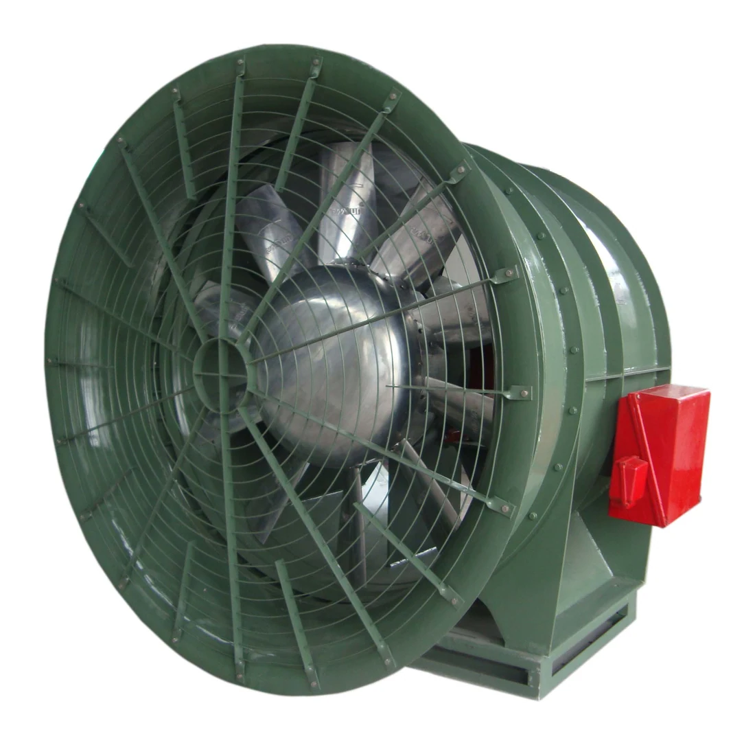
The fan casing is only one part of the installed geometry. TWOSUN shows DTF configurations with an inlet flare and flexible-connection arrangements, while the wider range includes silencers and dampers. Check the assembly from the upstream connection to the downstream connection. Omitting these components from the first layout can leave insufficient space for the intended airflow path or maintenance work.
A DTF inlet flare needs room to do its job
An inlet flare provides a defined entry arrangement, so its available approach space should be shown on the drawing. Do not position a wall, abrupt turn or stored equipment immediately in front of the selected inlet simply because the flange still fits. Give the supplier the nearby geometry for review. The installed entrance should be assessed as part of the air route rather than as a decorative addition to the fan.
For general engineering background, AMCA discusses how adverse inlet and outlet conditions can reduce installed performance. In a DTF submission, that principle translates into a concrete request: include the actual adjacent ductwork and accessories when reviewing the selected operating point.
Consider a fan room where a silencer has been shortened to make space for a maintenance walkway. That change may alter both the acoustic proposal and the resistance used in fan selection. It should return to the coordinated technical review rather than remaining a civil-layout adjustment. Likewise, moving a damper closer to the inlet can change the conditions presented to the fan. The fan, silencer and damper drawings need a common revision basis.
DTF(R) vertical arrangements need their own support and removal plan
TWOSUN lists a DTF(R) vertical axial configuration alongside other DTF arrangements. Treat the mounting direction as a defined equipment requirement, with the support arrangement and handling route shown. A horizontal drawing turned through a right angle does not establish a suitable vertical installation. Confirm the selected construction, service access and load information with the equipment supplier and the project’s responsible structural designer.
Vertical placement can also change how technicians reach components or remove the assembly. Establish whether the fan is serviced in place, lowered or lifted through an opening. The catalogue describes removable connection sections for maintenance on certain DTF arrangements; your drawing should identify the actual removable sections and available travel. Do not approve a maintainability statement that depends on space the finished fan room will not contain.
Separate DTF blade adjustment from reversible ventilation
TWOSUN’s range includes a variable-blade DTF configuration as well as DTF(R) equipment. These descriptions answer different questions. Blade adjustment concerns how the impeller setting relates to operation or selection. Reversible operation concerns airflow direction and the required performance in each direction. A specification that requests both should state both, without treating either label as shorthand for the other.
The small-size DTF description in the metro catalogue identifies a statically adjustable blade arrangement. Its construction notes describe adjustment with the fan stopped. That matters when a project expects air volume to change during operation. A stopped adjustment procedure is different from an actuated blade-control requirement. Confirm which arrangement is proposed before the controls contractor assumes that a live positioning signal will be available.
For a project with changing ventilation demand, discuss the proposed control method together with the selected fan and motor. Record whether the operating points are achieved by speed control, blade setting or another agreed arrangement. The technical submission should identify the permitted operating range and any restrictions. It should not promise unlimited turndown or arbitrary reversal simply because the equipment can be connected to a control cabinet.
Mechanical construction needs the same precision. The TWOSUN DTF literature describes the impeller, motor, casing, supports and vibration isolation as parts of the assembly, and discusses direct drive for the described configuration. Confirm the delivered arrangement on the selected drawing, including the relevant inspection and service provisions. A photograph of a similar DTF unit cannot establish the bearing access or motor details for the order.
Keep DTF axial fans and SDS jet fans on the correct system schedules
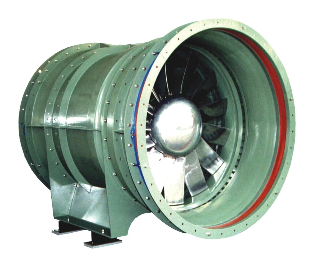
The SDS and SDS(R) jet-fan families belong in the same overall tunnel portfolio but should remain distinct in the design documents. A DTF unit is selected against a ducted system duty. A jet-fan assessment focuses on its contribution to longitudinal air movement and the tunnel installation. Comparing the two by nominal airflow alone can obscure their different functions.
A contractor buying both types should use separate acceptance descriptions. The DTF schedule needs its airflow-pressure duty and connection details. The SDS schedule needs the relevant thrust and directional requirements, together with the installation arrangement. Common purchase administration is useful, but merging these technical descriptions into one generic tunnel fan line can create confusion at inspection and site receipt.
Supporting components should also follow the correct equipment reference. A DTF damper or silencer must correspond to its duct connection and operating modes. An SDS silencer belongs to its own jet-fan assembly and performance assessment. TWOSUN supplies these product routes, allowing coordinated discussions, but the project submission still needs to identify which accessory belongs to which unit and how it affects the relevant duty.
Release the DTF drawing with manufacturing and test requirements attached
An effective DTF interface record assigns a separate identifier to each operating mode. The ventilation schedule, selected curve and control description can then refer to that identifier. This is particularly useful where two fan rooms have similar equipment but different emergency functions. It prevents a curve approved for routine ventilation in one room from being mistaken for the complete acceptance basis of another unit.
For a DTF(R) proposal, distinguish the forward and reverse connection conditions in that record. A shared fan does not mean the two external air routes impose identical resistance. Describe the relevant damper positions and connected route in each mode, then ask for the corresponding technical assessment. The difference belongs in the engineering submission rather than being left for commissioning personnel to discover through a low-flow complaint.
Blade-setting information should also survive the drawing process. If a DTF is selected at a particular static setting, preserve that information with the equipment reference and agreed verification documents. If an adjustable arrangement is specified, establish the permitted adjustment method and who is responsible for it. A generic variable-blade description can otherwise conceal the difference between a factory selection setting and a controllable operating function.
Access to the DTF motor connection and any agreed monitoring points needs to be shown with the finished services in place. A connection box facing a wall can create an avoidable installation problem even when the main casing fits. Ask the mechanical and electrical installers to review those locations together. The supplier’s general arrangement provides the equipment information, while the site drawing must demonstrate the actual working clearance.
For a fan delivered with separate flexible connections or an inlet flare, identify which interfaces the site fabricator must provide. The contractor should know where the manufacturer’s supply ends and where the site ductwork begins. Keep dimensions and fixing details on the accepted drawing. That boundary is especially useful when fabrication occurs in different workshops and a late mismatch would affect both the fan-room layout and the installation schedule.
The final DTF submission should therefore be checked as a connected set of interfaces, not only as a machine drawing. Mode references explain the air duty, the assembly drawing explains the space, and the agreed control description explains operation. Each must retain the same selected fan identity before manufacturing and site preparation proceed on separate schedules.
TWOSUN’s manufacturing and testing capability includes aerodynamic measurement, balancing, material checks and production inspection. For a metro order, agree the evidence needed for the actual DTF reference: performance basis, approved configuration, inspection records and any project-specific witness requirements. General laboratory capability is valuable, but the equipment-specific test scope must be clear before production milestones are fixed.
If certified performance is specified, verify the model and relevant catalogue directly. The AMCA directory for Zhejiang Shuangyang lists particular DTF and DTF(R) series. Match the proposed equipment to the applicable listing rather than extending that scope to every DTF photograph or historical catalogue entry. Association membership alone is a different kind of evidence.
Make the shipment arrangement follow the approved fan-room interface. A large DTF assembly may need a defined receiving and lifting route, while removable connection sections or accessories need clear identification if shipped separately. TWOSUN’s delivery information shows wooden export packing and coordination support. Agree protection, lifting information and the supplied component list for the selected assembly; do not leave those decisions to the unloading crew.
One final review should bring the ventilation engineer, controls contractor and installation team to the same revision. Confirm the normal and emergency modes, the complete connected length, the mounting direction and the maintenance opening. When those four subjects are settled together, the DTF order can move from a catalogue selection to equipment that the fan room can actually accommodate and the operating team can understand.
Where the project also uses longitudinal jet ventilation, compare SDS(R) Bidirectional Jet Fan Supplier Review for Two-Way Tunnel Duties.
